new year's high resolution
Here it is, first post of the new year on the last day of my almost-four-week break from work. The time off has been awesome because I’ve gotten so much down. Apart from various parties and outings and other festivities, most of the first two weeks were spent organising the garage in a pretty serious way. I took almost all of my old computer gear to the local tip (who are participating in the Byteback program, making my culling reasonably environmentally-friendly). This is a pretty big thing for me, as I’m a hoarder and had kept all sorts of stuff (mostly for sentimental reasons) dating back to 1982. I’ve kept one working model of every computer and console I had for posterity and/or hacking, but have thrown all the extras and all the PC stuff I had that I’ll likely never use. I’ve kept a few things that might have some actual monetary or other value as collectables, and I’ll put those up on eBay when I get around to it.
As a result of all this, my garage has just about nothing in it, so I’ve set up a desk and sorted all my various electronics bits, tools and whatever so they’re all nicely labeled and accessible. I even put in some halogen lights so the whole place is extremely well lit and I can see what I’m doing. And no computer in sight, though I am dragging the laptop out there with me.
All of this is to support this weeks’ new hobby, which is getting back into hardware hacking in a pretty serious way. I’m not sure if its as a result of general burnout or because I’m now write code for my job rather than hacking to support my job as I was previously, but I found towards the end of last year that I just had no brain for code by the time I got home. I’m thinking that perhaps hardware is close enough to what I know to hold my interest and not be completely impossible, but different enough that there’s room in my brain for it. Time shall tell.
Anyway, back in May I bought a RGB-to-HDMI converter and did some work to get my Amiga going on my LCD TV. As I mentioned then, my next project was to get RGB out of my Nintendo 64 so that I could play it without it looking horrible. I began work on what seemed like a fairly modest project: to build Tim Worthington’s N64 RGB DAC using discrete logic rather than a CPLD (which at the time seemed way to complicated).
At the time I didn’t really want to commit any money to this project as I didn’t know if it was something that I was actually capable of doing. Since I had some stripboard, connectors and most of the other parts I’d need I opted to just build the thing on stripboard and buy the few chips and resistors that I’d need.
In hindsight this turned out to be the wrong decision. Routing data buses on stripboard means a lot of bits of wire flying around, and it doesn’t help that the board has to be small to fit inside the case. Over the course of the next couple of months I got perhaps three-quarters of the way there, and after a big effort in the last two weeks I produced this monstrosity:
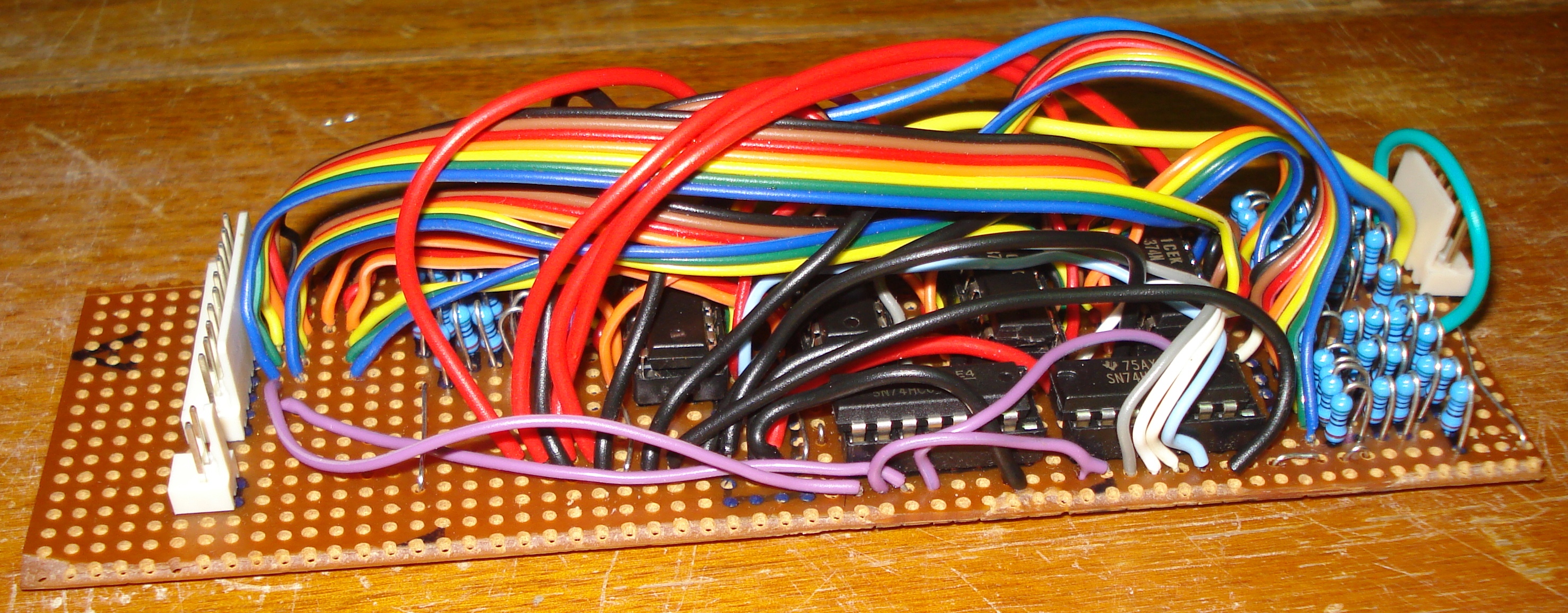
Yeah, I know. There’s more pics on Flickr but it doesn’t get any prettier.
There’s not much to it. Its four data latches (one for each of red, green and blue and one for the control lines), a couple of support chips and three R2R ladders.
In spite of the mess I still had high hopes for it, so I hooked it up and to my great surprise it (sorta) worked. Here’s what Super Mario 64 looks like on my TV with the standard composite cable:
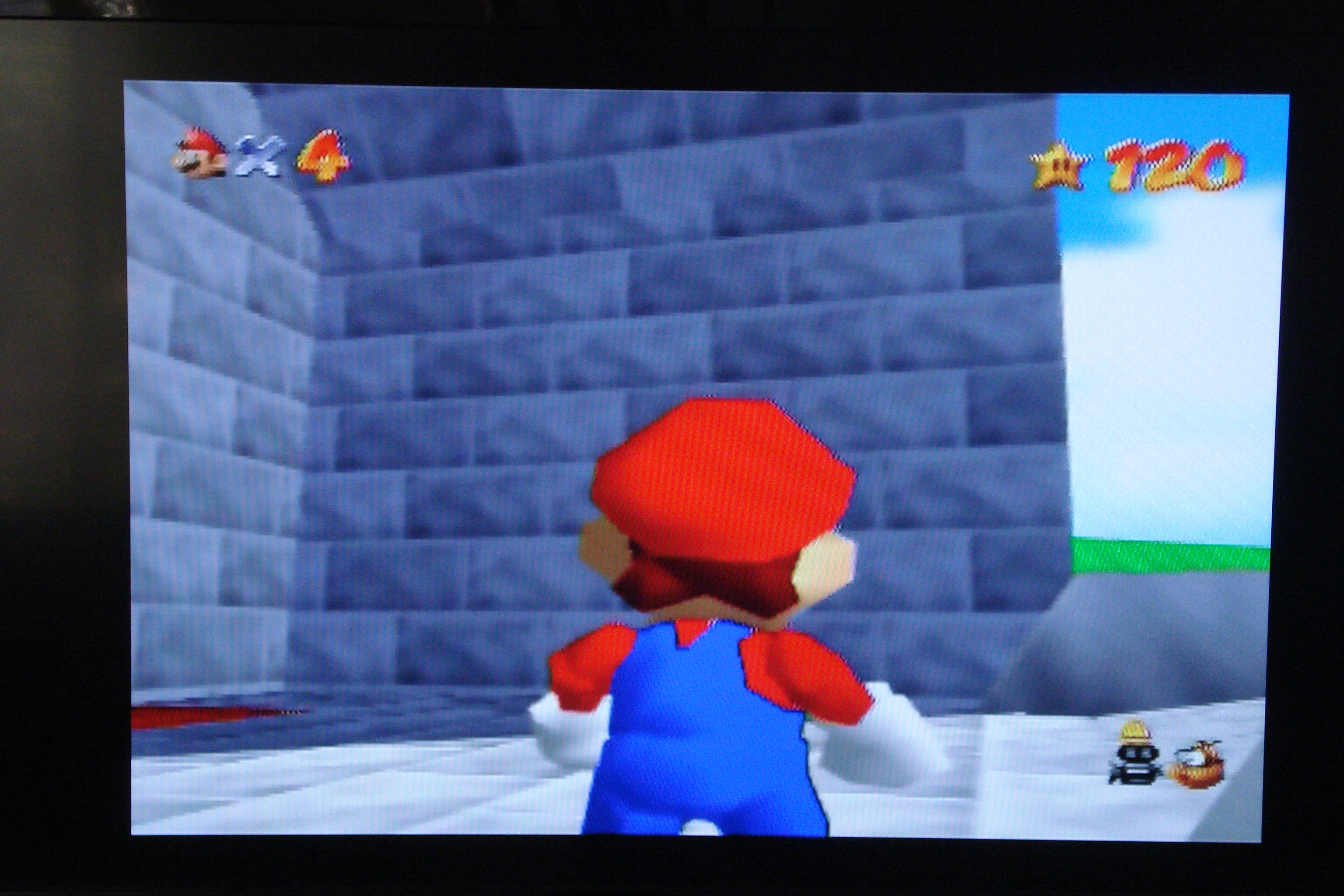
The major thing I’m trying to fix here is the weird “hatching” effect on high-contrast edges (like the life/star counters). Its not bad in static screens, but once things start moving its a horror on the eyes; its pretty much impossible to play.
But, with the magic of wires, we get this:
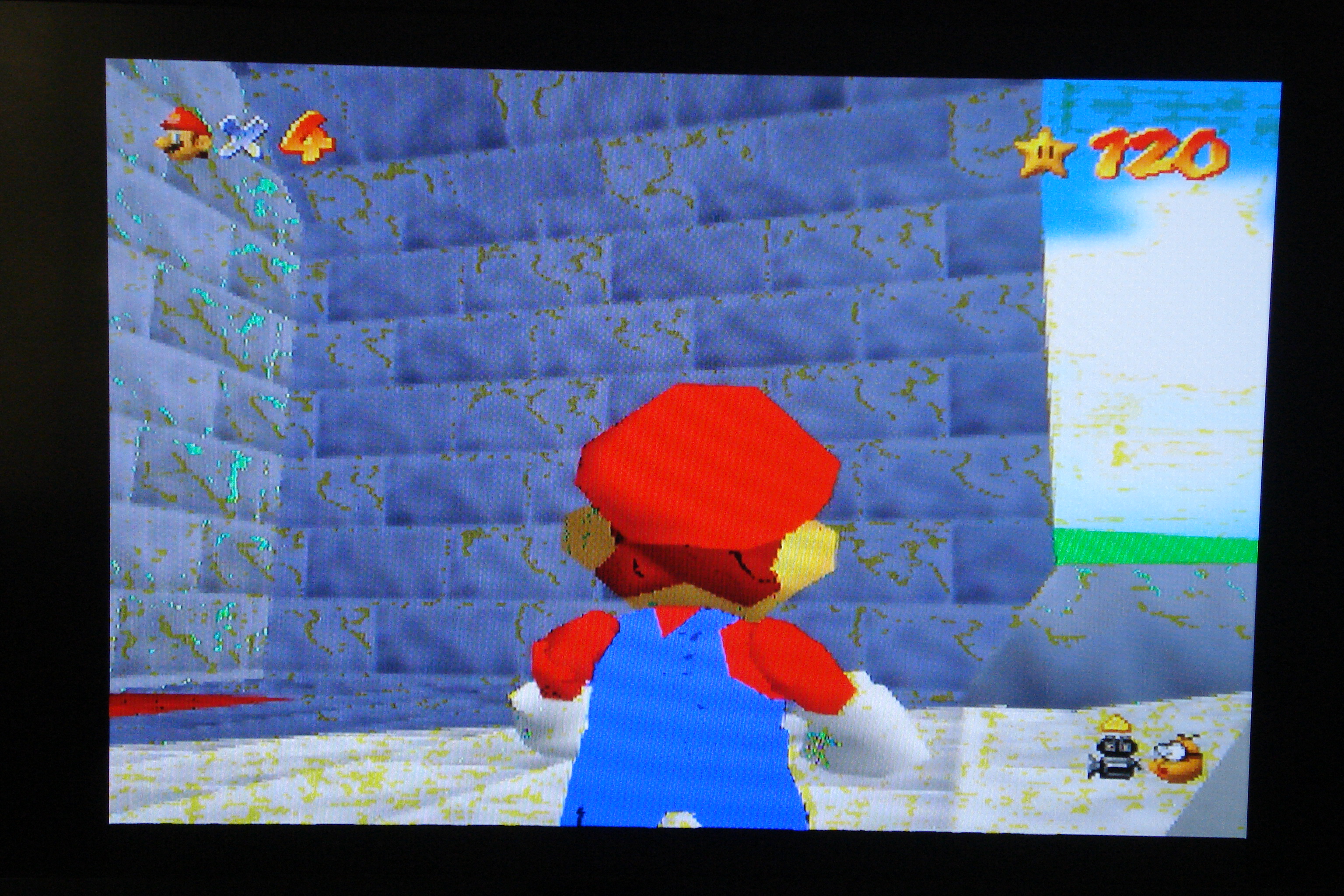
As you can see, everything is nice and crispy, which is was the desired result. Some of the colours are off though, which obviously isn’t right.
Another example, this time from Yoshi’s Story:
Composite:
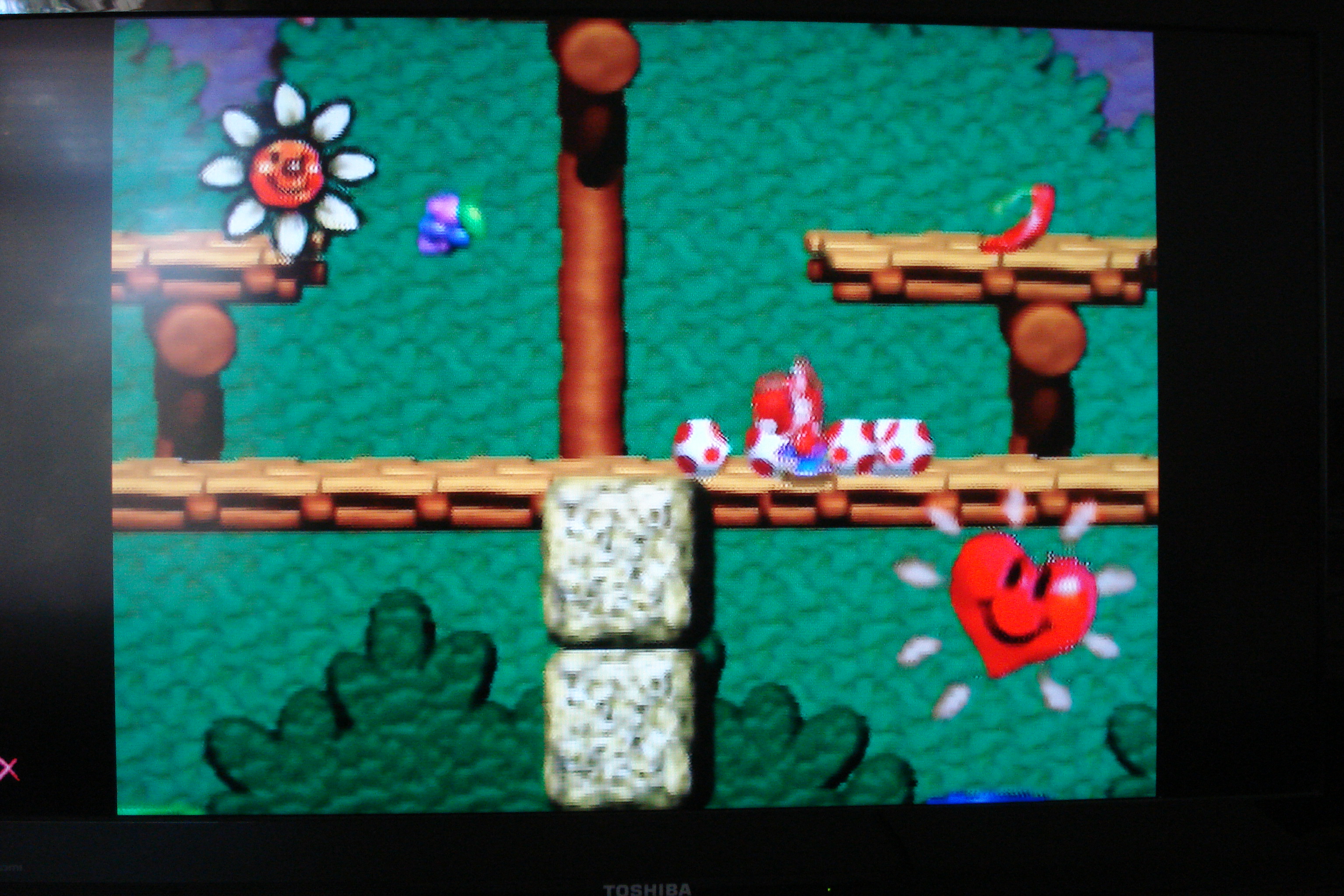
RGB:
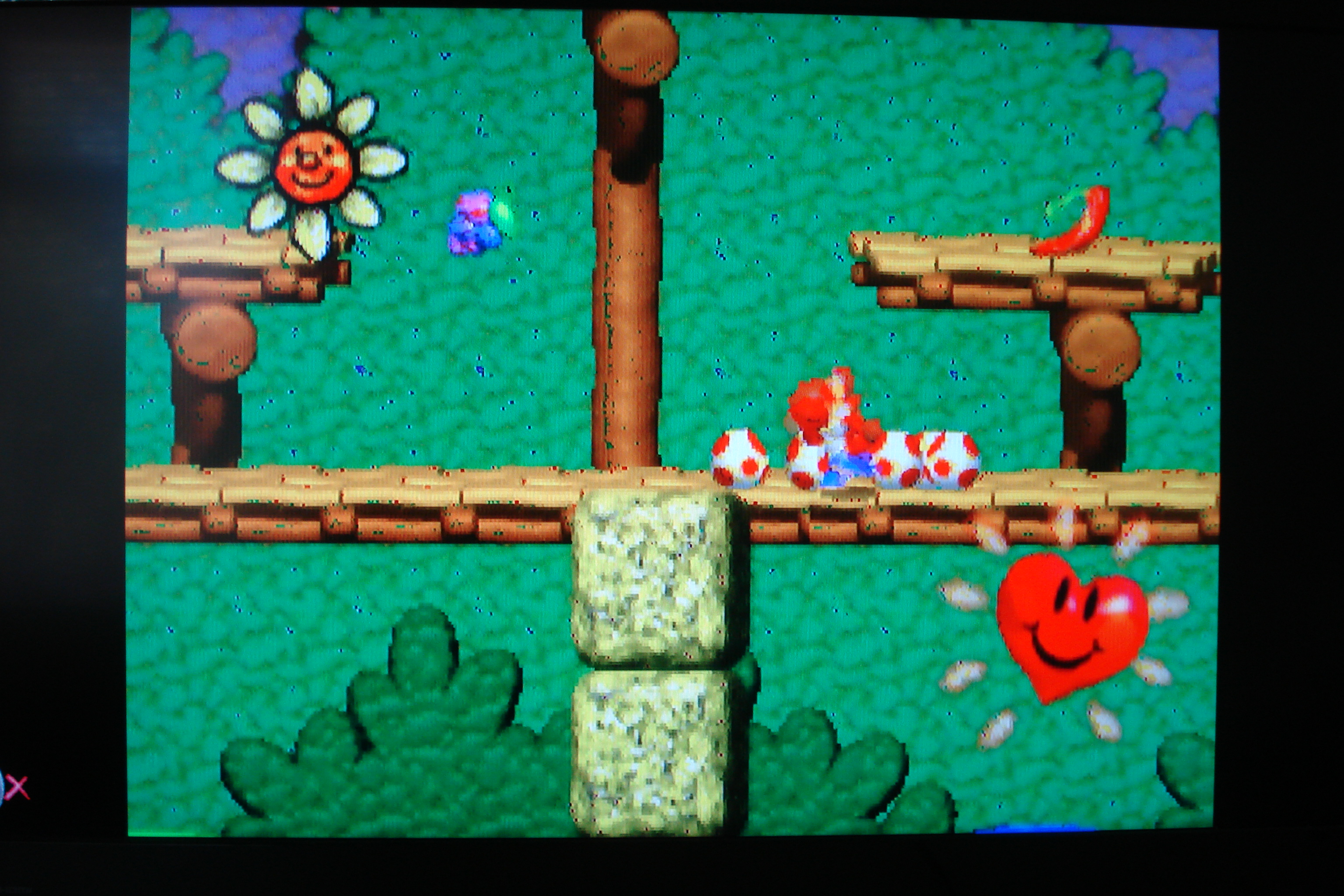
I haven’t had the chance to really think about it in depth but with the way that the colours are generally brighter and Mario’s clothes are washed out, and the way the other colours appear, my gut feeling is that I’ve wired the inputs to the R2R ladders wrong in such a way that they’re off by one bit. With the board being so insane though I figured I have pretty much no chance of debugging it and even if I do figure it out its going to kill my fingers to try and make any changes to the board.
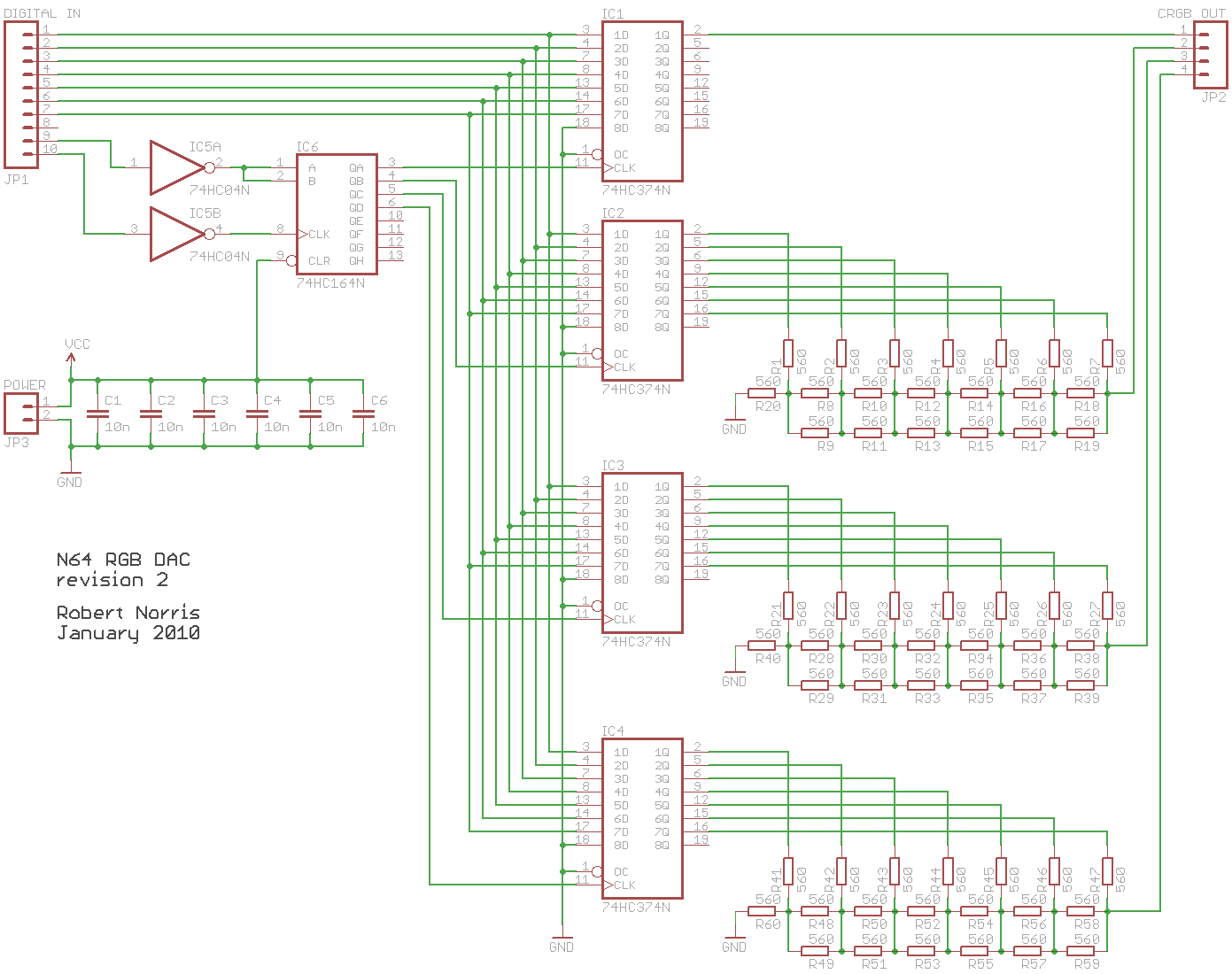
Actually getting the damn thing to work though has given me a lot of confidence and so I’ve decided to build it again, but this time done right, which means a real PCB. So over the last week I’ve been teaching myself how to use Eagle, a circuit and PCB designer that seems to be pretty popular. The learning curve is pretty steep, but I’ve made some good progress with it.
The first thing you do is draw the circuit. I’ve pretty much just copied Tim’s design, getting this:
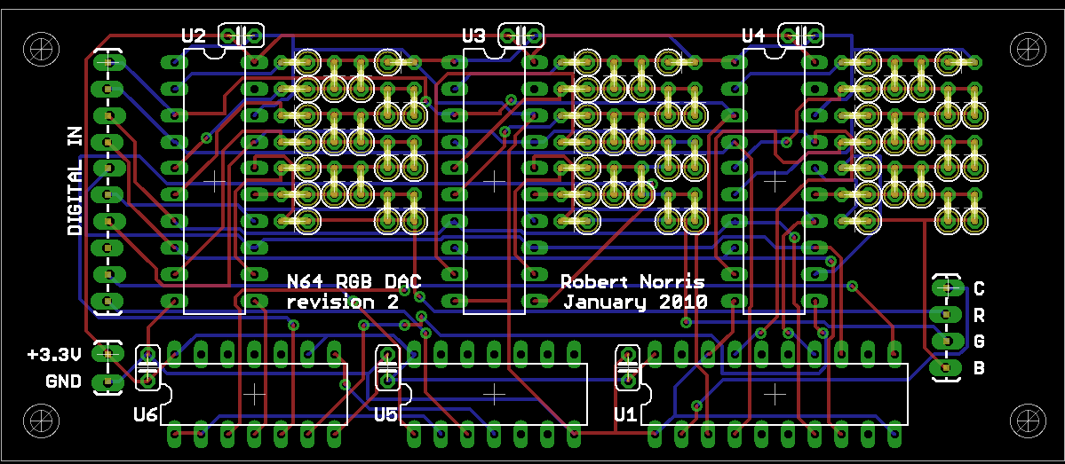
Next comes the board layout. Its pretty straightforward: setup the board size, place the components, then add all the wire routes to the board. The last bit is made simple using Eagle’s autorouter. Various forums and whatnot suggest that real board designers don’t use the autorouter, but I don’t care - it seems like it will work well enough and I’m just a noob here so I’ll take all the help I can get.
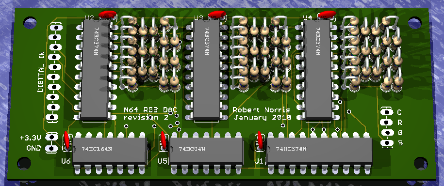
I also found a wonderful little program called Eagle3D which produced 3D renders of Eagle boards, including components. I ran mine through it to see what it would look like and got this:
Top side:
Bottom side:
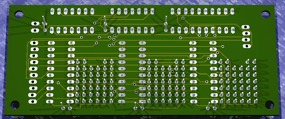
I’m feeling pretty good about this! I’ll sit on this for a couple of days just to make sure I’ve got it right, then I’ll send it off to BatchPCB, a PCB fabrication service that will do short runs (even one) for reasonable prices.
I’ve no doubt that I’ve missed something, and it won’t work properly the first time, but at least this board can be debugged. I see some good looking games in my future :)